Something with the equivalent features could be built into a watch with todays tech

MANDATORY DISCLAIMER! What I describe on this page is dangerous and stupid. It involves messing with a mains-powered supply and etching a circuit involves dangerous chemicals. There is currently a patch shaped like japan in my garage from where the acid spilled.
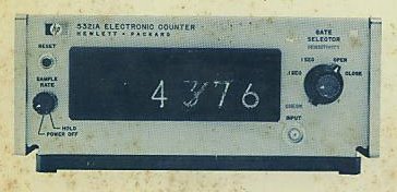
I'm a cheapskate, and as a result most of my components are hand-me-downs from my father's lab. Thanks to a lifetime of raiding the hamvention junk piles and the labs of former employers, the HoA labs has better equipment than the average student hobbyist's lab. One of the many random devices I've found in my sometimes frightening basement was an HP frequency counter. It predates my birth by several decades, and was built back when HP was a company that I would have given any two toes and a pinkie to work at. The thing is built like a rock, still works perfectly and the manual contains full parts list, a complete circuit diagram and a description of the theory of operation. The counter is a 4 digit counter with .1 or 1 second frequency intervals good to up to several megahertz and a nixie tube display. This last bit is what caught my eye.
Something with the equivalent features could be built into a watch with todays tech
Nixie tube clocks, like binary clocks, are something of a staple of the tinkering community. The nixie tube provides a warm glowing warming glow not present in conventional LED based clocks, and just ooze retro-geek style. The downside of the nixie tube design is that it requires a large number of high voltage components which can be hard to get. The nixie tube counter has the driver circuit built in, and it occurred to me that I could set the clock to an arbitrary time by simply counting up. This also leaves me with a perfectly good (and potentially useful) frequency counter.
The idea is simple. The first two digits are the hours, the last two are minutes. Every minute, pulse the timer and it will go up by 1. Every hour (when the time is, for instance, 11:59), send 41 pulses and the timer will count up to the next hour. Every 24 hours, count up from 2400 to 0000 and you roll back to midnight. Some counters have a reset function, so going from 2400 is just a matter of pulsing another port, but this counter would have required modification to be able to do that, and since it only has four digits available the count up method can be used to roll the clock to zero in about 2 minutes at 60hz.
The implementation uses my favorite microcontroller, the ATTiny 2313. This uC has 18 general purpose I/O pins (14 more than required) and a "generous" 2k of memory. Complete overkill for this project, but it's the only chip I had on hand, and the one I have the most experience with. Two lines are dedicated to push buttons to set the hour and the minute, another is used to pulse the counter, and a fourth is used to get the 60 Hz signal from the outlet. Since it took only a single line of code to do (benefit of memory mapped I/O), I set one of the port blocks to output the seconds, so wiring up 6 LEDs gives the true-binary representation of the number of seconds.
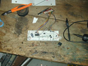
On the breadboard. (click for annotations)
The hardware design was also simple. The power supply was the only part I didn't have in my collection. Since I was getting the time from the 60 Hz line signal, an AC output wallwart instead of a typically rectified and filtered DC supply was needed. AC only transformers are not common (but occasionally used by PC speakers), but it's trivial to convert a DC output wallwart into an AC one by bypassing the rectification circuitry. I used a 4.5 volt transformer that came with a long dead CD player. Disassembling the transformer is fairly easy. They're usually glued together, some have a few tabs, but generally sawing through one of the corners along the seam (attack the end that has the 110vac plug coming out, as the other end generally has rectification circuitry that can be damaged) allows levering open the case and access to the (potentially lethal) innards. If it's plugged in at this time, you may die. This transformer gave out 11 volts AC with no load, a bit more after rectification and filtration. A 7805 fixed 5 volt regulator was added to convert the voltage into something the AVR could use.
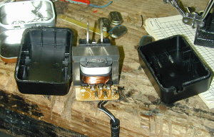
Dissassembled power supply. (click for annotations)
A separate line wired directly from the transformer (before the was run through a voltage divider to keep the voltage at safe levels for the microcontroller's inputs. This signal is used for debouncing and to control the rate the nixie counter control pulse is run at. Commented source code (released under the BSD license) and installable HEX file is available below.
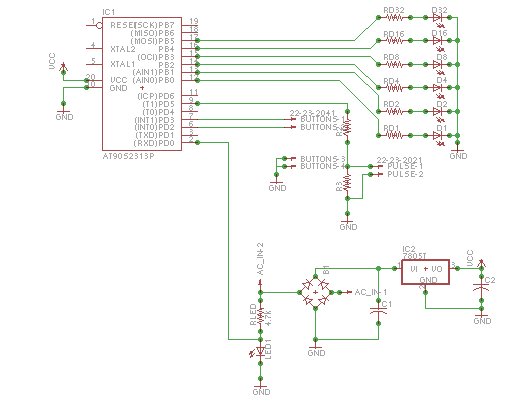
Circuit schematic (click for annotations)
A personal requirement for useless projects such as this is that I learn something at the end. Since this is pretty much a rehash of the binary clock, I had to tack something on to the project to justify wasting my time on it. "It's cool" is valid, but I have a number of other ideas in the works that fit that. I decided that making a custom circuit board was a valid vehicle for this particular project. I had long ago vowed to never use Verio board again, and yet I found myself stubbornly stripping wires, flipping the board up and down, and cursing the fundamental difficulty of point to point soldering. Patching mistakes, solder bridges, and just finding the nearest ground gave me a big headache all because I was too lazy to invest the time it took to etch my own copper clad. Hopefully I can now declare my days of Verio prototyping to be over.
The first hurtle was designing the circuit board. I used CadSoft Eagle, because the Old Bald Guy recommended it and it had a free Linux client. There's a steep learning curve to this software, but once you get over it, it's relatively easy to use and a good deal more powerful than I'm likely to need. I used the procedure detailed in Gootee's website to create the board. There's a number of other writeups detailing the process, but Gootee's had the most detailed information on things like paper selection and etchant. In a nutshell, turning copper clad board into a functional circuit board had 3 basic steps: Toner transfer, etch, and drill. The copper clad board and drill bits I acquired from the Dayton Hamvention, the etching chemicals from a local hardware store. The copper clad was double sided and came in strips that were approximately 4 inches wide by 3 feet long and cost $1.50. The first attempt used copper clad picked up from Radio Shack, but it was expensive, the board was brittle and not all stores carry it.
Most companies that do printed circuit boards take Gerber format files. Eagle exports to this, but for toner transfer etchings, it's easier to print straight from Eagle. Select the layer 1 and pads channel on the board window, and click print. Make sure 'reverse' is not selected for the circuit traces. The eagle files and a PDF of the leads suitable for toner transfer is available in the link below
I have Some experience with toner transfer already, so this was not that difficult. The technique that Gootee recommended was to use a clothing iron, and that worked well enough for me. I ground a spare tip for my soldering iron to a smooth hemisphere and gave the paper an additional rubdown.
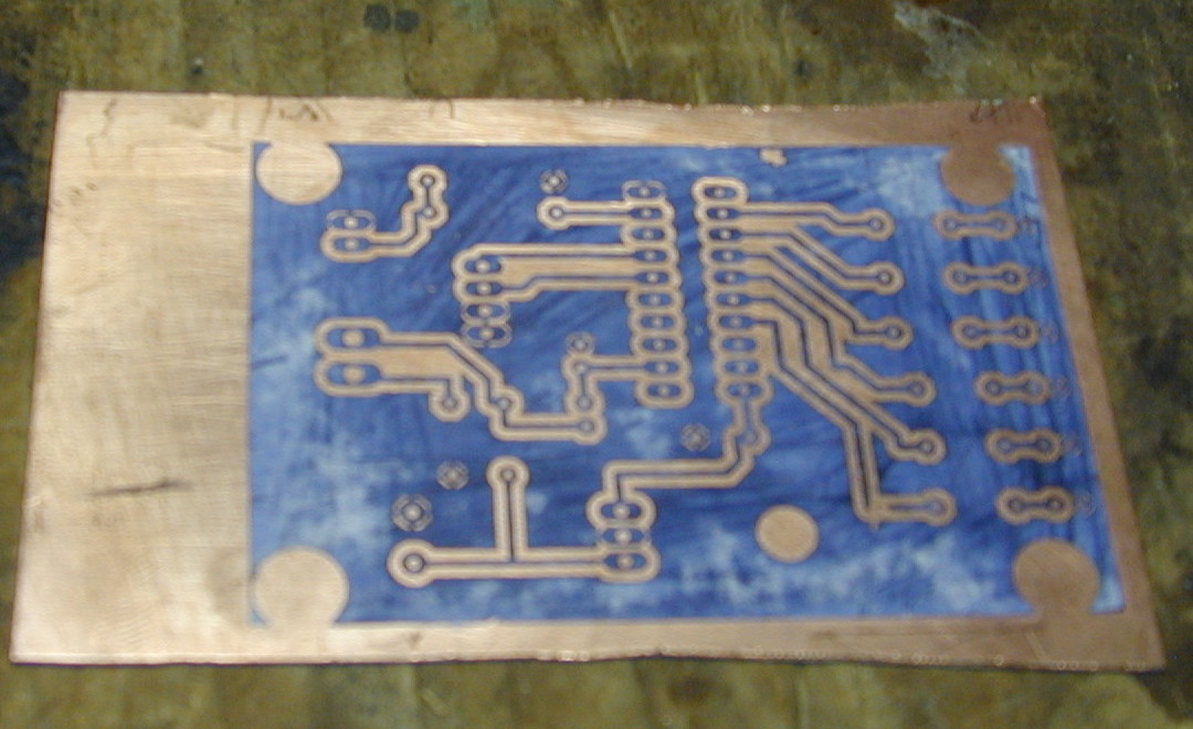
Toner transfer results
The etchant was two parts hydrogen peroxide to one part muriatic acid. The acid is quite dangerous, having fumes that you don't want to breath, especially after inhaling your first lungfull. Goggles and ventilation are in order, but care must be taken to stand upwind of the solution. When mixing, do as you aught to and add the acid to the water (or in this case, 3% hydrogen peroxide in an aqueous solution). Since my housemates instituted a draconian policy of no corrosive/explosive/flammable chemistry in the house, I did the work in the garage. The initial attempt was done in February, and it
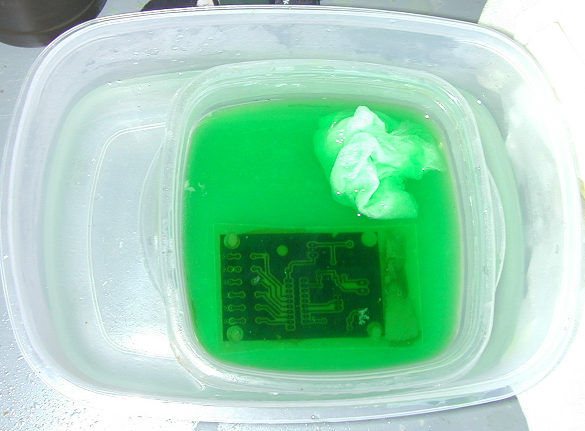
Etching the circuit
Drilling PCBs requires smaller drill bits than most hardware stores carry. The smallest I was able to find anywhere was 1/16, which is much too big. Some experiments with poking holes in sheets of paper with the drills showed that most components required a minimum of 70mm diameter drills, and the voltage regulator required 85mm drills. I used an old bench drill press that predates me by a wide margin. The drill press was technically variable speed, in that you could move the belt between different wheels to get different rates. I used the highest speed (3150 RPM), and had no problems with punching through the board. Lots of light is a must to hit the holes square on, though, and I have several that I had to punch through twice. Next time I try this I believe I will tin the pads before drilling on the assumption that the solder will help position the drill tip.
Assembly was amazingly easy compared to point-to-point wiring. I skipped adding a silkscreen layer as the board had a low enough parts count to work by reading the parts off of my laptop screen. The final design had a single glitch: The LED used in production was a different type than the LED used in breadboarding, and had a lower voltage drop. As a result the microcontroller couldn't get an effective 60hz signal. Replacing the LED with a voltage divider caused the design to work again. Care must be taken that the peak voltage of the signal not exceed 5.1 volts, and each transformer has a different output voltage.
The end result fit neatly in an altoids tin. I had a box of the male-female screw plugs that are used to hold DSub connectors in the back of the computer which I used to create a standoff from the bottom of the box. The output of the wallwart was wired directly to the board, and a BNC connector was run through the top of the tin to interface with the nixie counter. The next version I'm working on for my father is designed for a 6-tube counter that's resettable. This one will have seconds in addition to hours and minutes, and reset it's self instead of counting up and rolling over.
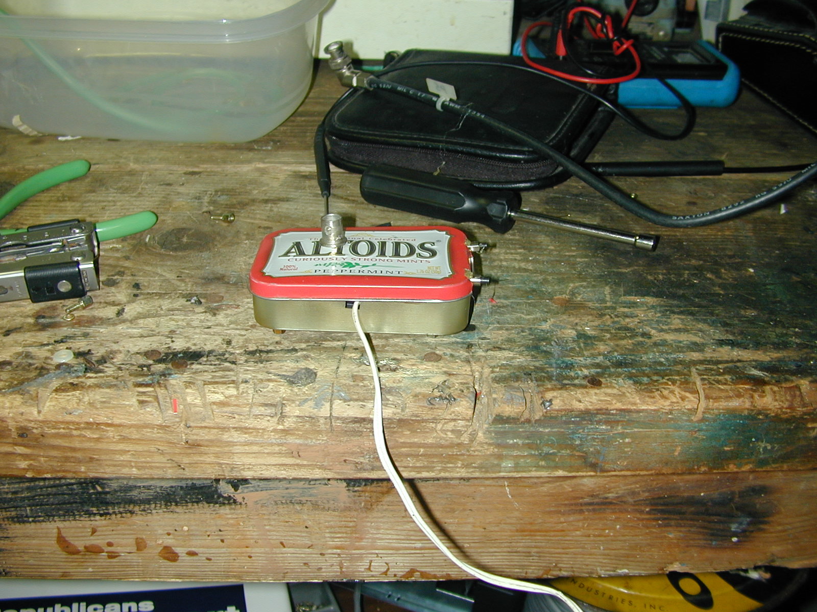
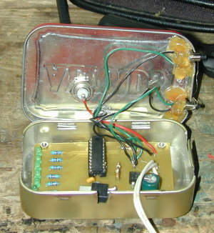
The finished box (click for annotation)
The cadsoft schematic and board files, a printable PDF of the circuit, the source code and a compiled HEX file sutable for uploading can be found in this zip file or in this bzip'd tar archive.
If you wish to comment on this mod, send me an email at p@ohbah.com
Return to index.


All works on this page are copyright 2009 Patrick Tait. Some rights reserved: 